


|
namlosh posted:But it's working, perfectly, trust me Nice! I usually like to celebrate key wins by electrocuting myself unintentionally. E. Oops, that was supposed to be a dumb self deprecating joke, not sarcasm Cory Parsnipson fucked around with this message at 06:04 on Dec 12, 2022 |
 #
?
Dec 12, 2022 02:57
#
?
Dec 12, 2022 02:57
|
|


|

|
| # ? May 9, 2024 13:20 |
|
|
So I have a question regarding Lithium battery balancing... I've got a bunch of these TP4056 charging modules and I've gotten pretty good at charging a single cell with them and all that. I also have a ton of small batteries scavenged from disposable crap. Sort of like a way less charming and knowledgeable Big Clive. I'd like to take some of those batteries and run them in series to get double the voltage out. Do I need to match internal resistances in order to do this safely? And if I can pull that off, then when I'm charging, would I hook up a TP4056 to each battery? or is it not that simple? Are there any resources online I can learn more about this? I'm not trying to do more than 2 in series, and wouldn't even care to do that really except that most boost convertors I have require DC-in to be greater than the 3.7 put out by a single lithium cell. I'm literally just trying to convert some things over to using these scavenged lithium cells. And just to be clear, they're tiny cells. Any danger should be pretty minimal with < 500mAh batteries. I'm not trying to string a bunch of 18650s together. I feel like someone mentioned doing this recently in the thread, but I couldn't find it when I looked.
|
|
#
?
Dec 12, 2022 03:52
|
|

|
whats with all the rhino haircut avatars these days?
|
|
#
?
Dec 12, 2022 05:15
|
|

|
ryanrs posted:I've been playing around with UV adhesives for stuff like that (wire tacking, misc assembly). Today I discovered that while 365nm UV LEDs are pretty neat, they have almost zero penetration of acrylic. I got a 395nm flashlight and it works much better for curing through the plastic. this is actually something you can look up for future reference   395nm is right on the border but there will be decent transmittance. 365nm is past the wall.
|
|
#
?
Dec 12, 2022 06:30
|
|


|
namlosh posted:I've got a bunch of these TP4056 charging modules and I've gotten pretty good at charging a single cell with them and all that. I also have a ton of small batteries scavenged from disposable crap. Sort of like a way less charming and knowledgeable Big Clive. Something else to keep in mind is that the individual cells might not have protection circuitry if they relied on their original device for that.
|
|
#
?
Dec 12, 2022 17:12
|
|

|
Check this out. This guy built a larger 555 out of tubes. https://youtu.be/Erdep7XInWU . He also built a whole computer out of tubes too, a lot smaller than the original gymnasium sized ones of the past.
|
|
#
?
Dec 12, 2022 23:29
|
|
|
Gymnasium is one of the more underrated semiconductors
|
|
#
?
Dec 13, 2022 00:26
|
|

|
I've been watching too much technology connections. Got a set of old incandescents for 3 euros. They look lovely, they use 28 watts. My big 100ft outdoor setup with bulbs uses about 40 watts. They run on direct 230V and there are 20 of them, so 233/20 = 11.5 that says 12V ~1W lamps to me. Two of them are blinking lights and they make the whole thing blink, real annoying. And my computer speakers would hiss in tune with the blink! I tried replacing them with resistors just to see if it was only those two that where responsible. Using a killawatt I could tell they used 0.09 amps, so know amps and voltage I calculated I needed 2422 ohms, and I took that divided by 20, so 120 ohms per light. So a 120ohm 1W resistor should do it. It got very hot very fast though, I don't know if the resistors where 1W they just looked to be that size but you don't really know for sure. I want to replace them with proper replacements. They shine powerfully I tihnk at 1W, I was thinking I could use a triac based dimmer to reduce them to 0.6W and they might draw like 14-15 watts which isn't a lot. Or would a PWM be better, I got a PWM already I dont use. Or I could get all new .6W lights, I did find those online. e: Scratch the PWM idea, not good for AC circuits I read. Or it's more involved at any rate. His Divine Shadow fucked around with this message at 09:13 on Dec 13, 2022 |
|
#
?
Dec 13, 2022 09:00
|
|

|
His Divine Shadow posted:Using a killawatt I could tell they used 0.09 amps, so know amps and voltage I calculated I needed 2422 ohms, and I took that divided by 20, so 120 ohms per light. So a 120ohm 1W resistor should do it. It got very hot very fast though, I don't know if the resistors where 1W they just looked to be that size but you don't really know for sure. Regardless of the size or power rating, a resistor dissipating 1W is going to... dissipate 1W. The power rating only really affects the physical size (and therefore how much mass that gets spread out into and how much surface area there is to get rid of it), at least until you get up into the big chonky resistors that have metal bodies and heatsinks and stuff like that. If you're running a 1W resistor at anything close to 1W it's going to get real hot, real fast. The power rating just means that it won't exceed its maximum rated temperature at that power level (which is still usually something ridiculous for resistors, like well over 100C, since they're designed to run hot for this exact reason) if it's free-standing in air. Sorry if you already knew this I just feel it needs pointing out because I have been (quite literally) burned before by a resistor that was the "correct" power rating.
|
|
#
?
Dec 13, 2022 09:12
|
|


|
I didn't know for sure, but I was thinking 1w in a small package might be hot regardless.
|
|
#
?
Dec 13, 2022 09:15
|
|
|
Resistors power ratings reflect their max temperature, which is way higher than a lot of other components (e.g. chips). So a resistor being run at max power rating is hot. Really hot. I oversize my power resistors by a lot.
|
|
#
?
Dec 13, 2022 10:03
|
|

|
I am on a christmas light binge recently, and old tech stuff is fascinating. I didn't know there used to be neon based christmas lights, they sure look cool and are pretty power efficient. https://www.youtube.com/watch?v=7MZYo-WcZRs
|
|
#
?
Dec 14, 2022 10:08
|
|
|
I got my thermal camera (and portable scope, later)  It's really cool but also I wanted to post about it here as I think it could be very useful for electronics stuff. This Infiray P2 Pro came with a macro lens which is a must for this application    That's the back of the cheapo usb load PCB, in the second image the big mosfet is in the top-right corner and there's clearly something getting way too hot here 
|
|
#
?
Dec 14, 2022 23:11
|
|

|
Hell yeah I use mine all the time for that reason
|
|
#
?
Dec 14, 2022 23:33
|
|
|
Yeah Mikeselectricstuff did a video on it and it seemed pretty nice, especially the whole "not hobbled by US export restrictions" thing.
|
|
#
?
Dec 14, 2022 23:45
|
|
|
His Divine Shadow posted:I am on a christmas light binge recently, and old tech stuff is fascinating. I didn't know there used to be neon based christmas lights, they sure look cool and are pretty power efficient. Neons were the LEDs of their day. If you had indicator lights in anything before 1980, it was neon. The craziest thing about neons is that you can make either pole glow depending on the DC direction, or both poles glow with AC. This property was used intentionally to cut down on the number of bulbs needed in some equipment. I know HP made decade counters for their frequency counters using only 5 bulbs: https://youtu.be/WrBPVVKvWfE kid sinister fucked around with this message at 02:13 on Dec 15, 2022 |
|
#
?
Dec 15, 2022 00:03
|
|
|
That phenomenon is also how the digit in a Nixie tube is illuminated selectively
|
|
#
?
Dec 15, 2022 00:23
|
|

|
My favorite bit of neon lore is that they work as memory. You can keep a bunch of them at whatever voltage they need to sustain a discharge, and if they've already been struck, they'll continue glowing. If they haven't, they won't start since the striking voltage is much higher than the sustaining voltage. This meant you could do things like have monochrome graphic terminals with gas plasma displays and no framebuffer back when semiconductor memory was super pricey.
|
|
#
?
Dec 15, 2022 01:27
|
|

|
Yeah the negative resistance weirdness of neon (and gas discharge tubes in general) is the much more interesting thing imo. A little while ago I was playing around with some triode vacuum tubes and wanted to make a blinker circuit, and figured I'd use neons since I'm already dealing with high voltage anyway. It did the slow on-off blink just fine, but due to the negative resistance whenever one would switch on it would oscillate on and off incredibly fast for a half a second in this very weird way that kinda trailed off.
|
|
#
?
Dec 15, 2022 01:53
|
|
|
Is anyone else noticing a strange shortage/pricing of decent quality SMT decoupling caps? DigiKey is showing 0.1uF, 50V, C0G/NP0, 1206 parts at like $0.20-$0.80 USD per unit right now. Especially strange as a bunch of semiconductors we use that have been out of stock for the last year or two suddenly all came on the market in the last week or so. Maybe the new chips being available is causing a run on caps since nobody's been able to build stuff reliably for two years.
|
|
#
?
Dec 15, 2022 07:40
|
|

|
Jameco's doing free shipping on orders over $50 with coupon code JOLLY if anyone wants some sacks of random 74-series CMOS chips: https://www.jameco.com/z/GB220-JAMECO-CMOS-CD4000-74C-74HC-and-74HCT-Series-Grab-Bag-100-pcs-_2288751.html e: Or this UV-erasable EPROM which is a new product somehow?? https://www.jameco.com/z/27C64-250-Major-Brands-UV-Erasable-CHMOS-EPROM-64K-8Kx8-5V-CDIP-28_2336511.html Do they even still make those? Shame Boy fucked around with this message at 13:32 on Dec 15, 2022 |
|
#
?
Dec 15, 2022 13:26
|
|
|
Shame Boy posted:Yeah Mikeselectricstuff did a video on it and it seemed pretty nice, especially the whole "not hobbled by US export restrictions" thing. Is the main restriction is the capped framerate? The 24fps is definitely nice and pleasant. Probably not a huge deal for electronics but a big general quality of life improvement.
|
|
#
?
Dec 15, 2022 14:28
|
|
|
mobby_6kl posted:Watched it after I already received mine lol. I think he posts on eevblog, that's where I found some early recommendations for this. I'd disagree a bit about the macro lens not being completely necessary, in my first example shot you can see the hot sport, but not which one of the three components it is. I'm sure you could figure it out but macro makes it much faster and easier. The framerate was the one I knew about but googling it just now there is predictably a bunch of other weird specific rules I assume exist because a heat seeking missile used an IR sensor with specs like that at one time or another: quote:Most countries can purchase uncooled microbolometer based, 9 Hz thermal imaging cameras without restriction. This depends on the sensor size and pixel pitch. For example, an ICI 9640 S, 9 Hz 640 x 480 microbolometer camera with 17 um pixel pitch can be exported to most non embargoed countries. Thermal cameras with pixel pitch smaller than 17 um may be an issue as determined by the U.S. Department of State. Thermal imaging cameras with 640 x 512 pixel resolution and up can be purchased by any country except U.S. Embargoed countries such as North Korea, Iran, Venezuela, etc as long as the frame rate is slowed to 9 Hz. Also, most ICI cameras have Commodity Jurisdiction (CJ) Code for them, but others do not. North Korea throws their hat on the ground and jumps up and down on it after being foiled by the lack of an extra 32 pixels of width
|
|
#
?
Dec 15, 2022 15:06
|
|
|
What will happen if I have two types of incandescents in a series connection? The majority of the bulbs are rated 90mA while the new ones are 45mA. I am not sure but I think the 90mA ones will shine less while the 45mA ones will shine normally?
|
|
#
?
Dec 17, 2022 17:42
|
|
|
This is a good application of basic circuit laws. The current draw alone isn't enough information, but I assume they are both designed for the same voltage, and then that is enough to do the calculations. I'll say they're designed for 24v for simplicity. Technically it doesn't matter what voltage we're talking about -- the ratio between the two is all that matters -- but I am going to use 24v to illustrate the math. By Ohm's law, the bulb drawing 90mA at 24v has a resistance of 267 ohms, and the 45mA bulb has a resistance of 533 ohms. The two together in series add up to 800 ohms. Two resistors in series form a voltage divider. By Kirchoff's laws, the voltage gains and drops in any circuit loop must add up to zero. 24v will be dropped across both bulbs, and the ratio of this drop depends on the ratio of the resistances. In the initial case, you have two identical 90mA/267 ohm bulbs in series. The math is very simple; each drops 12 volts. Power is voltage multiplied by current, so each bulb is running at 12 * 0.090 = 1.08W. Now you replace one 267 ohm bulb with the 533 ohm bulb. We redo the voltage divider calculation using the new ratio of resistances. It's clearly 1:2, but here's the math, assuming the lower resistance bulb is first: Vo = Vi * R1 / (R1+R2) Vo = 24 * 267 / 800 Vo = 8v As expected, the larger bulb (smaller resistance) will drop 8 volts and the smaller one (higher resistance) will drop the remaining 16. Now we can calculate the power drawn by each bulb, and thus the brightness. The first bulb still has a resistance of 533 ohms but now it is running at 16 volts. Again by Ohm's law, P = v^2 / R P1 = 16^2 / 533 P1 = 0.48W P2 = 8^2 / 267 P2 = 0.24W Oops. Your large bulb is running at about 1/4 the brightness than it was before, and your small bulb is running at less than half its nominal power (or about 10% less than if you just had two of the small bulbs in series). Now, if you have many many bulbs in sequence the effect of replacing a few of them will be less dramatic. But replacing some of the bulbs with new ones that have double the resistance will definitely have an effect. What is the context here? Are these christmas lights? I don't think I've seen christmas lights wired in plain series since I was a little kid. Sagebrush fucked around with this message at 18:39 on Dec 17, 2022 |
|
#
?
Dec 17, 2022 18:27
|
|
|
Yeah vintage christmas string lights, 80s perhaps, 20 bulb string running on 230v mains and 12V per bulb.
|
|
#
?
Dec 17, 2022 18:55
|
|
|
Okay, so in that case it's not really a big deal. Doubling the resistance of one bulb would be the equivalent of adding an extra one to the end of the strand. The whole string will get marginally dimmer, but you won't blow anything up. The greater concern to me is just that these 45mA bulbs, if all else is equal, will all be dimmer than the older 90mA bulbs. They're simply drawing less power and I don't think incandescent technology has really advanced since the 1980s. They'll look different from the old ones they're replacing.
|
|
#
?
Dec 17, 2022 19:01
|
|
|
Ah, I did find 25 spares all 45mA so I could potentially replace all the lights in the string.
|
|
#
?
Dec 17, 2022 20:06
|
|
|
mobby_6kl posted:I got my thermal camera (and portable scope, later) Check your data sheet but 83�C case temp on a MOSFET might not indicate a junction temp of concern. Never hurts to spread the heat around if it's concentrated though.
|
|
#
?
Dec 17, 2022 21:41
|
|

|
The best thing I ever found with a thermal camera was a tiny 50Mhz oscillator IC which the assembly place had installed in the wrong orientation, so +3.3V was being fed into its output and its power input was ground. It was running at 120C or so. I just desoldered it and for a laugh resoldered it in the correct orientation. It worked perfectly.
|
|
#
?
Dec 17, 2022 21:50
|
|

|
That's largely been my experience, too. I YOLO prototype PCBs into power now with no current limiting, while watching with the camera. Particularly when my power supply sections get hot quickly, I can shut it off before any real damage happens, and then I know the issues is somewhere downstream of that particular voltage regulator. Side note, I once accidentally fed 12V into a circuit with a PIC running a simple blink program. It blinked properly for a good 5-10 seconds before it gave up the ghost.
|
|
#
?
Dec 18, 2022 00:51
|
|
|
I don't have room at my work station for a deskmounted magnifier/lamp but as I'm getting into finer detailed work I realize I need something to magnify the work area. Are there recommended brands or styles of head-mounted magnifiers? I see some that are branded for jewelers and then others that look like they're out of a bladerunner knockoff.
|
|
#
?
Dec 18, 2022 02:30
|
|

|
ante posted:That's largely been my experience, too. I YOLO prototype PCBs into power now with no current limiting, while watching with the camera. Particularly when my power supply sections get hot quickly, I can shut it off before any real damage happens, and then I know the issues is somewhere downstream of that particular voltage regulator. What I love about thermal cameras is that I can find shorts even with current limiting, as you can see even pretty small temperature increases. I consider them critical lab equipment now, as it's often nearly impossible to find a short without one (I have done the hillbilly equivalent test where you jam 2A or more and see what physically burns, but this can permanently damage the board in the process so the camera is preferred). I usually try and design circuits so that every sub circuit has a ferrite bead or 0 ohm link on the power in. That lets me systematically isolate stuff, which is useful both for hunting short circuits and also low power design when I'm trying to find what's drawing power. But when it's someone else's design this isn't often an option.
|
|
#
?
Dec 18, 2022 02:42
|
|

|
DR FRASIER KRANG posted:I don't have room at my work station for a deskmounted magnifier/lamp but as I'm getting into finer detailed work I realize I need something to magnify the work area. I've had a pretty good experience with using a little magnifier + LCD like shown below rather than a head mounted unit. I did eventually build a wider platform for it to support larger boards. 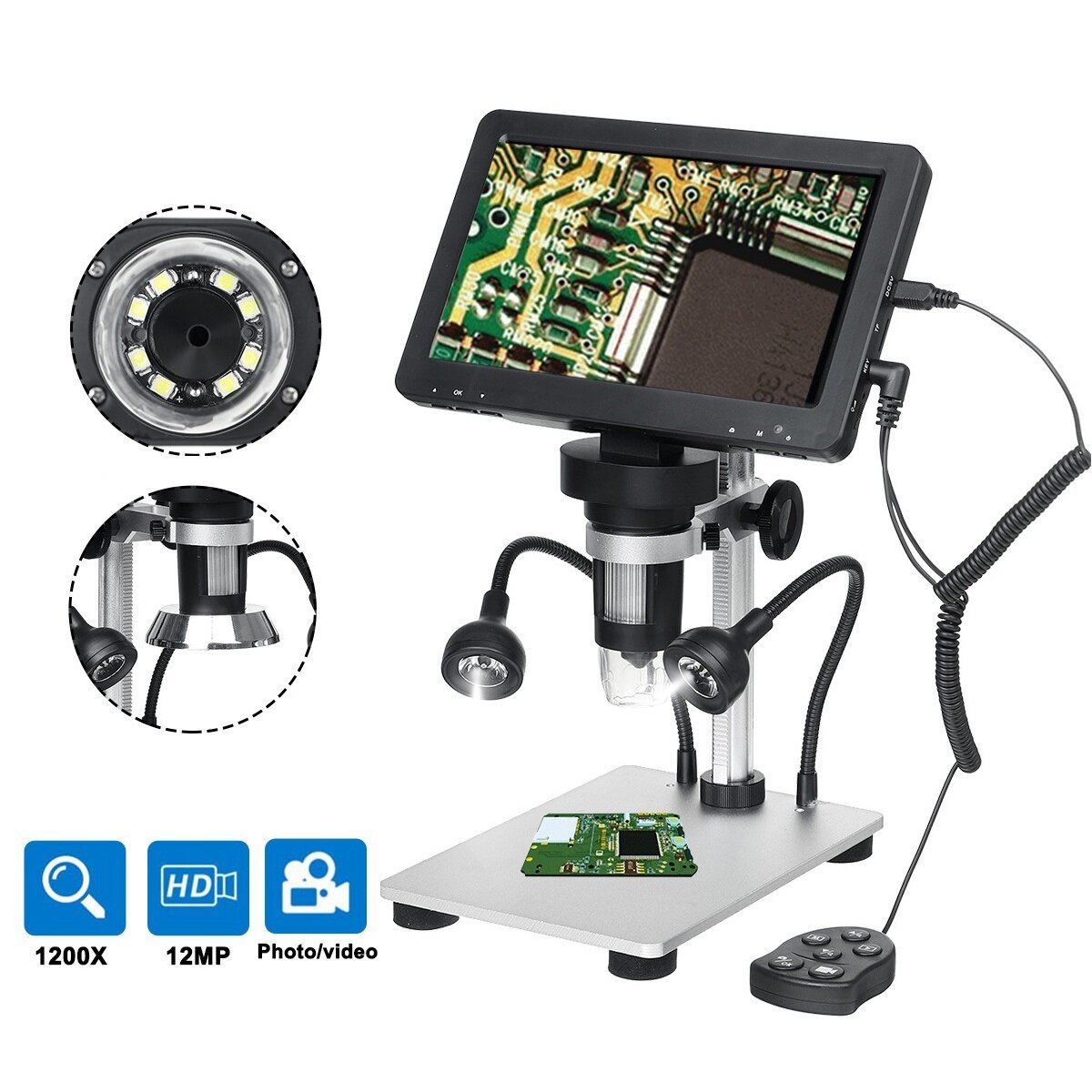 My main go-to is still a magnifier on a swing arm with a ring light. 
|
|
#
?
Dec 18, 2022 02:44
|
|
|
Splode posted:I consider them critical lab equipment now, as it's often nearly impossible to find a short without one (I have done the hillbilly equivalent test where you jam 2A or more and see what physically burns, but this can permanently damage the board in the process so the camera is preferred). We have some lock-in amplifiers at work, I've been able to find shorts by running the output sine wave from the lock-in through a little transimpedance amp that then connects across the power inputs of whatever you're trying to find the short in. That sets up a managed sine wave current that goes out and finds the short while leaving a magnetic field behind that is oscillating at the transmit frequency of the lock-in. On the input side of the lock-in I put a small inductive pickup (basically just a tiny inductor mounted on the end of an old ink pen with a BNC cable attached). You can wave the pickup probe around the board and the lock-in detects when you're close to the short circuit path. I kind of want to build one of these as a stand-alone unit with an audio output that gets louder/higher pitched when the pickup probe is getting a strong signal so that I don't have to keep looking back and forth between the PCB and the lock-in display.
|
|
#
?
Dec 18, 2022 02:52
|
|
|
PDP-1 posted:We have some lock-in amplifiers at work, I've been able to find shorts by running the output sine wave from the lock-in through a little transimpedance amp that then connects across the power inputs of whatever you're trying to find the short in. That sets up a managed sine wave current that goes out and finds the short while leaving a magnetic field behind that is oscillating at the transmit frequency of the lock-in. On the input side of the lock-in I put a small inductive pickup (basically just a tiny inductor mounted on the end of an old ink pen with a BNC cable attached). You can wave the pickup probe around the board and the lock-in detects when you're close to the short circuit path. Wow that's really cool! If you do build this please either sell them or consider publishing the design somewhere - I want one!
|
|
#
?
Dec 18, 2022 02:55
|
|
|
I�m looking for some helping hands to hold smallish pcbs for soldering. I�m seeing a few different sorts and am not sure which would suit me best. There are the more classic ones like this: https://www.amazon.com/ProsKit-900-...ps%2C170&sr=8-4 Octopus looking ones: https://www.amazon.com/Soldering-Fl...s%2C170&sr=8-10 And ones with a larger base plate: https://www.amazon.com/SainSmart-Ma...s%2C170&sr=8-15 Should I avoid specific types?
|
|
#
?
Dec 19, 2022 23:02
|
|


|
I have the first one you linked, trash tier, do not buy.
|
|
#
?
Dec 19, 2022 23:08
|
|
|
The first one is the old-fashioned style and they're totally fine...if you get a good one. I still have the one I got from Radio Shack in like 1993 and it's great and works perfectly. I've added a couple of extra arms to it too. The 10 dollar knockoffs on Amazon, however, are much more cheaply made -- they base is noticeably much smaller, so they're like half the weight and they tip over, and the alligator clips regularly fall off. They only barely do the job. Unfortunately I don't know how you would identify a good one just from Amazon descriptions. Haven't tried the gooseneck kind yet.
|
|
#
?
Dec 19, 2022 23:26
|
|
|

|
| # ? May 9, 2024 13:20 |
|
|
I just pulled the first links I found on Amazon to illustrate what types I came across. I am not looking to buy the cheapest one I can find.
|
|
#
?
Dec 19, 2022 23:50
|
|